MP Board Class 10th Science Solutions Chapter 13 Magnetic Effects of Electric Current
MP Board Class 10th Science Chapter 13 Intext Questions
Class 10th Science Chapter 13 Intext Question Page No. 224
Question 1.
Why does a compass needle get deflected when brought near a bar magnet?
Answer:
A compass needle get deflected when brought near a bar magnet because a compass needle is in fact, a small bar magnet. The ends of the compass needle point approximately towards north and south directions.
Class 10th Science Chapter 13 Intext Questions Page No. 228
Question 1.
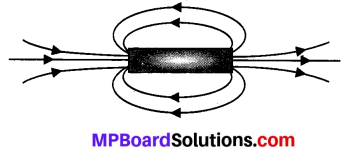
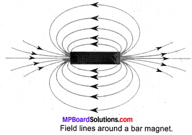
Draw magnetic field lines around a bar magnet.
Answer:
Magnetic field lines of a bar magnet emerge from the north pole and terminate at the south pole. Inside the magnet, the field lines emerge from the south pole and terminate at the north pole.
Question 2.
List the properties of magnetic field lines.
Answer:
The properties are:
- They travel from north pole to south pole outside the magnet and south pole to north pole inside the magnet.
- They are closed and continuous curves.
- Two magnetic field lines never intersect each other. If the lines intersect, then at the point of intersection there would be two directions [the needle would point towards two directions] for the same magnetic fields which is not possible.
- The number of field lines per unit area is the measure of the strength of magnetic field, which is maximum at poles. The magnetic field is strong, where the field lines are close together and weak where the lines are far apart.
Question 3.
Why don’t two magnetic field lines intersect each other?
Answer:
Two magnetic fields lines of force never intersect each other. If the lines intersect, then at [the point of intersection there would be two directions [the needle would point towards two directions] for the same magnetic field, which is not possible.
![]()
Class 10th Science Chapter 13 Intext Questions Pages No. 229. 230
Question 1.
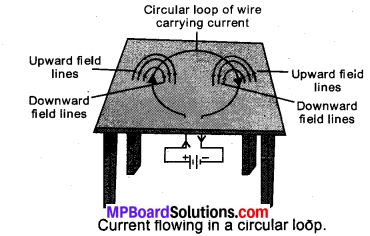
Consider a circular loop of wire lying in the plane of the table. Let the current pass through the loop clockwise. Apply the right-hand rule to find out the direction of the magnetic field inside and outside the loop.
Answer:
Inside the loop = Pierce inside the table.
Outside the loop = Appear to emerge out from the table.
For downward direction of current flowing in the circular loop, the direction of magnetic field lines will be as if they are emerging from the table outside the loop and merging in the table inside the loop. Similarly, for upward direction of current flowing in the circular loop, the direction of magnetic field lines will be as if they are emerging from the table outside the loop and merging in the table inside the loop, as shown in the given figure.
Question 2.
The magnetic field in a given region is uniform. Draw a diagram to represent it.
Answer:
The magnetic field lines are parallel and equidistant.

Question 3.
Choose the correct option.
The magnetic field inside a long, straight, solenoid-carrying current
(a) is zero
(b) decreases as we move towards its end
(c) increases as we move towards its end
(d) is the same at all points
Answer:
(d) The magnetic field inside a long, straight, current-carrying solenoid is uniform. It is the same at all points inside the solenoid.
Class 10th Science Chapter 13 Intext Questions Pages No. 231,232
Question 1.
Which of the following property of a proton can change while it moves freely in a magnetic field? (There may be more than one correct answer.)
(a) mass
(b) speed
(c) velocity
(d) momentum
Answer:
(c) velocity
(d) momentum.
Question 2.
In Activity 13.7, how do we think the displacement of rod AB will be affected if
- current in rod AB is increased;
- a stronger horse-shoe magnet is used; and
- length of the rod AB is increased?
Answer:
- displacement of A is increased.
- If a stronger horse-shoe magnet is used magnetic field is increasing.
- current flows is more.
Question 3.
A positively-charged particle (alpha-particle) projected towards west is deflected towards north by a magnetic field. The direction of magnetic field is
(a) towards south
(b) towards east
(c) downward
(d) upward
Answer:
(d) upward.
Since the positively charged particle alpha particle projected towards west, so the direction of current is towards west. Now the deflection is towards north, so the force is towards north. Now hold the forefinger, centre finger and thumb of our left – hand at right angles to one another. Let us adjust the hand in such a way that our centre finger points towards west and thumb points towards north. If we look at our forefinger, it will be pointing, upward. Thus, the magnetic field is in the upward direction. So, the correct answer is (d).
Class 10th Science Chapter 13 Intext Questions Page No. 233
Question 1.
State Fleming’s left-hand rule.
Answer:
According to this rule, stretch the thumb, forefinger, and middle finger of your left hand such that they are mutually perpendicular. If the first finger points in the direction of the Magnetic field and the second finger in the direction of current, then the thumb will point in the direction of motion or the force acting on the conductor.
Question 2.
What is the principle of an electric motor?
Answer:
A current-carrying conductor when placed in a magnetic field experiences a force. This is the principle of an electric motor.
Question 3.
What is the role of the split ring in an electric motor?
Answer:
The split ring reverse the direction of current in the armature coil after every half rotation i.e., it acts as a commutator. The reversal of current reverses, the direction of the forces acting on the two arms of the armature after every half rotation. This allows the armature coil to rotate continuously in the same direction.
![]()
Class 10th Science Chapter 13 Intext Question Page No. 236
Question 1.
Explain different ways to induce current in a coil.
Answer:
The different ways to induce current in a coil are as follows:
(a) If a coil is moved rapidly between the two poles of a horse-shoe magnet, then an electric current is induced in the coil.
(b) If a magnet is moved relative to coil, then an electric current is induced in the coil.
Class 10th Science Chapter 13 Intext Questions Page No. 237
Question 1.
State the principle of an electric generator.
Answer:
An electric generator works on the principle of electromagnetic induction. It generates electricity by rotating a coil in a magnetic field.
Question 2.
Name some sources of direct current.
Answer:
Some sources of direct current are cell, Dc generator, etc.
Question 3.
Which sources produce alternating current?
Answer:
AC generators, power plants etc., produce alternating current.
Question 4.
Choose the correct option:
A rectangular coil of copper wires is rotated in a magnetic field. The direction of the induced current changes once in each
(a) two revolutions
(b) one revolution
(c) half revolution
(d) one-fourth revolution
Answer:
(c) When a rectangular coil of copper is rotated in a magnetic field, the direction of the induced current in the coil changes once in each half revolution. As a result, the direction of current in the coil remains the same.
Class 10th Science Chapter 13 Intext Questions Pages No. 238
Question 1.
Name two safety measures commonly used in electric circuits and appliances.
Answer:
- Electric fuse
- Earthing wire.
Question 2.
An electric oven of 2 kW power rating is operated in a domestic electric circuit (220 V) that has a current rating of 5 A. What result do you expect? Explain.
Answer:
P = VI
Here P = 2 KW = 2000 W
V = 220
The current drawn by this electric oven is 9 A whereas the fuse in the circuit is ( only 5 A capacity. When a high current of 9 A flows through the 5 A fuse, the fuse wire will get heated too much, melt and break, the circuit. Therefore, when a 2 kW power rating electric oven is operated in a circuit having a 5 A fuse will blow off cutting off the power supply in this circuit.
Question 3.
What precaution should be taken to avoid the overloading of domestic electric circuits?
Answer:
- Each appliance has a separate switch to ON/OFF the flow of current through it.
- The use of an electric fuse prevents the electric circuit and the appliance from possible damage by stopping the flow of unduly high electric current.
- We should not connect too many appliances to a single socket to prevent overloading.
![]()
MP Board Class 10th Science Chapter 13 NCERT Textbook Exercises
Question 1.
Which of the following correctly describes the magnetic field near a long straight wire?
(a) The field consists of straight lines perpendicular to the wire
(b) The field consists of straight lines parallel to the wire
(c) The field consists of radial lines originating from the wire
(d) The field consists of concentric circles centered on the wire.
Answer:
(d) The magnetic field lines, produced around a straight current-carrying conductor are concentric circles. Their centres lie on the wire.
Question 2.
The phenomenon of electromagnetic induction is
(a) the process of charging a body
(b) the process of generating magnetic field due to a current passing through a coil
(c) producing induced current in a coil due to relative motion between a magnet and the coil
(d) the process of rotating a coil of an electric motor.
Answer:
(c) When a straight coil and a magnet are moved relative to each other, a current is induced in the coil. This phenomenon is known as electromagnetic induction.
Question 3.
The device used for producing electric current is called a
(a) generator
(b) galvanometer
(c) ammeter
(d) motor.
Answer:
(a) generator.
Question 4.
The essential difference between an AC generator and a DC generator is that
(a) AC generator has an electro-magnet while a DC generator has permanent magnet.
(b) DC generator will generate a higher voltage.
(c) AC generator will generate a higher voltage.
(d) AC generator has slip rings while the DC generator has a commutator.
Answer:
(c) AC generator will generate a higher voltage.
Question 5.
At the time of short circuit, the current in the circuit
(a) reduces substantially.
(b) does not change.
(c) increases heavily.
(d) vary continuously.
Answer:
(c) increases heavily.
Question 6.
State whether the following statements are true or false.
(a) An electric motor converts mechanical energy into electrical energy.
(b) An electric generator works on the principle of electromagnetic induction.
(c) The field at the centre of a long circular coil carrying current will be parallel straight lines.
(d) A wire with a green insulation is usually the live wire of an electric supply.
Answer:
(a) False
(b) true
(c) true
(d) False.
Question 7.
List two methods of producing magnetic fields.
Answer:
- Permanent magnet
- Electromagnet.
Question 8.
How does a solenoid behave like a magnet? Can you determine the north and south poles of a current-carrying solenoid with the help of a bar magnet? Explain.
Answer:
A solenoid is a long coil of circular loops of insulated copper wire. Magnetic field lines are produced around the solenoid when a current is allowed to flow through it. The magnetic field produced by it is similar to the magnetic field of a bar magnet. The field lines produced in a current¬carrying solenoid is shown in the following figure.
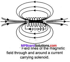
Fig. 13.4: Field lines of the magnetic field through and around a current carrying solenoid.
In the above figure, when the north pole of a bar magnet is brought near the end connected to the negative terminal of the battery, the solenoid repels the bar magnet. Since like poles repel each other, the end connected to the negative terminal of the battery behaves as the north pole of the solenoid and the other end behaves as a south pole. Hence, one end of the solenoid behaves as a north pole and the other end behaves as a south pole.
Question 9.
When is the force experienced by a current-carrying conductor placed in a magnetic field largest?
Answer:
The force experienced by a current -carrying conductor is the maximum when the direction of current is perpendicular to the direction of the magnetic field.
Question 10.
Imagine that you are sitting in a chamber with your back to one wall. An electron beam, moving horizontally from back wall towards the front wall, is deflected by a strong magnetic field to your right side. What is the direction of magnetic field?
Answer:
According to Fleming’s left-hand rule, the magnetic field acts in the vertically downward direction.
Note that the direction of current will be opposite to that of the electron beam.
Question 11.
Draw a labelled diagram of an electric motor. Explain its principle and working. What is the function of a split ring in an electric motor?
Answer:
An electric motor converts electrical energy into mechanical energy. It works on the principle of the magnetic effect of current. A current-carrying coil rotates in a magnetic field. The following figure shows a simple electric motor. When a current is allowed to flow through the coil MNST by closing the switch, the coil starts rotating anti-clockwise. This happens because a downward force
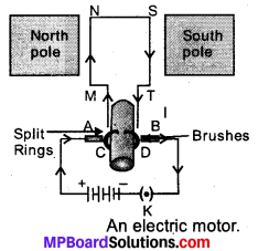
acts on length MN and at the same time, an upward force acts on length ST. As a result, the coil rotates anti-clockwise.
Current in the length MN flows from M to N and the magnetic field acts from left to right, normal to length MN. Therefore, according to Fleming’s left hand rule, a downward force acts on the length MN. Similarly, current is the length ST. flows from S to T and the magnetic fields acts from left to light, normal to the flow of current. Therefore, an upward force acts on the length ST. These two forces cause the coil to rotate anti-clockwise.
After half a rotation, the position of MN and ST interchange. The half¬ring D comes in contact with brush A and half-ring C comes in contact with brush B. Hence, the direction of current in the coil MNST gets reversed.
The current flow’s through the coil in the direction TSNM. The reversal of current through the coil MNST repeats after each half rotation. As a result, the coil rotate unidirectional ly. The split rings help to reverse the direction of current in the circuit. These are called the commutator.
Question 12.
Name some devices in which electric motors are used.
Answer:
Electric motor is used as an important component in electric fans, refrigerators, mixers, washing machines, computers, MP3 players etc.
Question 13.
A coil of insulated copper wire is connected to a galvanometer. What will happen if a bar magnet is
- pushed into the coil
- withdrawn from inside the coil
- held stationary inside the coil?
Answer:
- There is a momentary deflection in the needle of the galvanometer.
- Now the galvanometer is deflected towards the left showing that the current is now set up in the direction opposite to the first.
- When the coil is kept stationary with respect to the magnet, the deflection of the galvanometer drops to zero.
Question 14.
Two circular coils A and B are placed closed to each other. If the current in the coil A is changed, will some current be induced in coil B? Give reason.
Answer:
If the current in the coil A is changed there is a change in its magnetic field. By this electricity is induced in B. This is called Electromagnetic induction.
Question 15.
State the rule to determine the direction of a
- magnetic field produced around a straight conductor carrying current,
- force experienced by a current-carrying straight conductor placed in a magnetic field which is perpendicular to it, and
- current induced in a coil due to its rotation in a magnetic field.
Answer:
(i) Right-hand thumb rule: If the current-carrying conductor is held in the right hand such that the thumb points in the direction of the current, then the direction of the curl of the fingers will be given the direction of the magnetic field.
(ii) Fleming’slefthandrule: Stretch the forefinger, the central finger of the right hand mutually perpendicular to each other. If the forefinger points in the direction of the magnetic field, the central finger in the direction of the current, then the thumb points in the direction of a force in the conductor.
(iii) Fleming’s right-hand rule: Stretch the thumb/ forefinger and the central finger of the right hand mutually perpendicular to each other. If the forefinger points in the direction of the magnetic field, thumb in the direction conductor, then the central finger points in the direction of current induced in the conductor.
Question 16.
Explain the underlying principle and working of an electric generator by drawing a labelled diagram. What is the function of brushes?
Answer:
An electric generator converts mechanical energy into electrical energy. The principle of working of an electric generator is that when a loop is moved in a magnetic field, an electric current is induced in the coil, ft generates electricity by rotating a coil in a magnetic field. The following figure shows a simple AC generator.
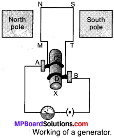
- MNST → Rectangular coil
- C and D → Two slip rings
- A and B → Brushes
- X → Axle, G → Galvanometer
If axle X is rotated clockwise, then the length MN moves upwards while length ST moves downwards. Since the lengths MN and ST are moving in a magnetic field, a current will be induced in both of them due to electromagnetic induction. Length MN is moving upwards and the magnetic field acts from left to right. Hence, according to Fleming’s right hand rule, the direction of induced current will be from M to N. Similarly, the direction of induced current in the length ST will be from S to T.
The direction of current in the coil is MNST. Hence, the galvanometer shows a deflection in a particular direction. After half a rotation, length MN starts moving down whereas length ST starts moving upward. The direction of the induced current in the coil gets reversed as TSNM. As the direction of current gets reversed after each half rotation the produced current is called an alternating current (AC).
To get a unidirectional current, instead of two slip rings, two split rings are used, as shown in the following figure.
In this arrangement, brush ‘A’ always remains in contact with the length of the coil that is moving up whereas brush B always remains in contact with the length that is moving down. The split rings C and D act as a commutator.
The direction of current induced in the coil will be MNST for the first rotation and TSNM in the second half of the rotation. Hence, unidirectional current is produced from the generator called DC generator. The current is called AC current.
Question 17.
When does an electric short circuit occur?
Answer:
If the resistance of an electric circuit becomes very low. Then the current flowing through the circuit becomes very high. This is caused by connecting too many appliances to a single socket or connecting – high power rating appliances to the light circuits. This results in a short circuit when the insulation of live and neutral wires undergoes wear and tear and then touches each other, the current flowing in the circuit increase abruptly. Hence, a short circuit occurs.
Question 18.
What is the function of an earth wire? Why is it necessary to earth metallic appliances?
Answer:
The metallic body of electric appliances is connected to the earth by means of earth wire so that any leakage of electric current is transferred to the ground. This prevents any electric shock to the user. That is why earthing of the electrical appliances is necessary.
![]()
MP Board Class 10th Science Chapter 13 Additional Important Questions
MP Board Class 10th Science Chapter 13 Multiple Choice Questions
Question 1.
Two magnet when come closer:
(a) Attract each other
(b) Repei each other
(c) Sometimes attract and sometimes repel
(d) No reaction
Answer:
(c) Sometimes attract and sometimes repel
Question 2.
Permanent magnet can be made by:
(a) Gold
(b) Carbon
(c) Alnico
(d) Wood
Answer:
(c) Alnico
Question 3.
When we draw magnetic field lines of any magnet it:
(a) Begin from N pole and end at S pole
(b) Begin from S pole and end at N pole
(c) Form circles around a magnet
(d) Form box around a magnet
Answer:
(a) Begin from N pole and end at S pole
Question 4.
Strongest magnetic pole around a magnet is
(a) Near North pole
(b) Near south pole
(c) In center of magnet
(d) At both poles
Answer:
(d) At both poles
Question 5.
Electro magnetism was discovered by
(a) Newton
(b) Oersted
(c) Ohm
(d) Joule
Answer:
(b) Oersted
Question 6.
Electro magnets are used in
(a) AC
(b) Fridge
(c) Radio
(d) All of these
Answer:
(d) All of these
Question 7.
Magnetic field are lines forming
(a) Straight lines
(b) Closed curves
(c) Dotted lines
(d) Dotted triangles
Answer:
(b) Closed curves
Question 8.
Magnetic field of a straight conductor form:
(a) Straight lines
(b) Concentric lines
(c) Points
(d) None of above
Answer:
(b) Concentric lines
Question 9.
According to right hand thumb rule, current is generated in a system:
(a) Parallel to magnetic field
(b) Perpendicular to magnetic field
(c) Just above the magnetic field
(d) All of these.
Answer:
(b) Perpendicular to magnetic field
Question 10.
If a circular loop conductor has 5 turn, magnetic field produced by it will be to than single loop conductor.
(a) 5 times bigger
(b) 5 times lesser
(c) Similar
(d) 10 times lesser
Answer:
(a) 5 times bigger
Question 11.
Magnetic field generated due to a passing current in a solenoid forms pattern:
(a) Similar to circular loops
(b) Similar to straight conductor
(c) Similar to Bar magnet
(d) Which is unique
Answer:
(c) Similar to Bar magnet
Question 12.
According to Fleming’s left hand rule
(a) Field is perpendicular to current
(b) Field is perpendicular to force generated
(c) Current is perpendicular to force generated .
(d) All of these
Answer:
(d) All of these
MP Board Class 10th Science Chapter 13 Very Short Answer Type Questions
Question 1.
What we call the end, where north end of freely hanged magnet stops?
Answer:
North pole.
Question 2.
Where force of a magnet can be detected?
Answer:
Near a magnet, in its magnetic field.
Question 3.
How we mark a magnetic force?
Answer:
With the help of magnetic field lines.
Question 4.
What do closer field lines of a magnet presents?
Answer:
Closer lines present stronger magnetic strength.
Question 5.
What is reason for different kinds of pattern of a magnetic pattern around a conductor generated magnetic field?
Answer:
Shape of conductor.
Question 6.
Give some examples of daily use where electro magnet is being used.
Answer:
Radio and Television.
Question 7.
How an electromagnet is formed?
Answer:
Electro magnet is formed by wrapping coil of insulated copper wire over core of soft iron.
Question 8.
What is experienced by a current carrying conductor when placed in a magnetic field?
Answer:
Force.
Question 9.
Who gave the theory of induced electromagnetic induction?
Answer:
Michael Faraday.
Question 10.
What is a galvanometer?
Answer:
An instrument which detects current in a circuit.
Question 11.
Give examples of appliances using electric motor.
Answer:
Electric pan, mixer, washing machines.
Question 12.
Which rule of electromagnetism suits best to express working of an electric motor?
Answer:
Fleming’s left hand rule.
Question 13.
What is the basic principle used in electric generator?
Answer:
It is based on electromagnetic induction.
Question 14.
What is the permissible value of electricity use in India?
Answer:
220 V, 50Hz.
Question 15.
How short-circuit can be prevented?
Answer:
By using fuse.
![]()
MP Board Class 10th Science Chapter 13 Short Answer Type Questions
Question 1.
Write two properties of magnet.
Answer:
- A magnet always points north or south when suspended freely.
- Like pole repel each other while opposite pole attract each other.
Question 2.
Define magnetism.
Answer:
A magnet influence its near by object and attracts towards itself, if magnetic in nature. This phenomenon is called magnetism.
Question 3.
Define magnetic field.
Answer:
Area under which a magnet can influence other magnetic objects is called its magnetic field.
Question 4.
Where we find closer line and what does it indicate?
Answer:
Closer lines show high strength of magnetic field while wide lines represents weak strength of magnet.
Question 5.
State Right hand thumb rule.
Answer:
Right hand thumb rule is represented by a down thumb fist in which fist represents a magnetic field while thumb represents current movement.
MP Board Class 10th Science Chapter 13 Long Answer Type Questions
Question 1.
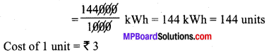
An electric heater rated 800 W operates 6h/day. Find the cost of energy to operate it for 30 days at ₹ 3.00 per unit.
Solution:
Power of the heater, P = 800 W Time, t = 6 hour /day
No; of days, n = 30 Cost per unit = ₹ 3.00
Total cost of its usage = ? Energy, E = P × t
Consumed in 1 day = 800 × 6 = 4800 Wh
Energy consumed in 30 days = 4800 × 30 = 144000 Wh
∴ Cost of 144 units = 3 × 144 = ₹ 432.
Question 2.
(a) Draw magnetic field lines produced around a current carrying straight conductor passing through cardboard. How will the strength of the magnetic field change, when the point where magnetic field is to be determined, is moved away from the straight wire carrying constant current ? Justify your answer.
(b) Two circular coils A and B are placed close to each other. If the current in the coil A is changed, will some current be induced in the coil B? Give reason.
Answer:
(a) (i) The magnetic field lines around a straight conductor carrying current are concentric circles whose center lies on the wire.
(ii) When a point where magnetic field is to be determined is moved away from the straight wire, the strength of the magnetic field decreases because as we move away from a current carrying straight conductor, the concentric circles around it representing magnetic field lines become larger and larger indicating the decreasing strength of magnetic field.
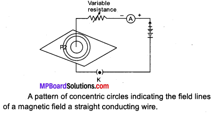
Fig. 13.18: A pattern of concentric circles indicating the field lines of a magnetic field a straight conducting wire.
(b) Yes, current is induced in the coil B. Because as the current in the coil A changes, the magnetic field lines around the coil B also change. Therefore, the change in magnetic field lines associated with the coil B is the cause of induced electric current in it.
Question 3.
(a) Draw magnetic field lines of a bar magnet. “Two magnetic field lines never intersect each other.” Why?
(b) An electric oven of 1.5 kW is operated in a domestic circuit (220 V) that has a current rating of 5 A. What result do you expect in this case? Explain.
Answer:
(a)
Two magnetic field lines do not intersect one another. The direction of magnetic field lines is always from north pole to south pole. If the two magnetic field line do intersect, it means at the point of intersection the compass needle is showing two different directions which is not possible.
(b) Power, P = 1.5 kW = 1.5 × 1,000 = 1,500 W
Voltage, V = 220 V, I = ?
P = V × I I = \(\frac { P }{ V } \) = \(\frac { 1,500 }{ 220 } \) = 6.8 A
Now, the current drawn by the oven is 6.8 A which is very high but the fuse in this circuit is only 5 A capacity. When a very high current of 6.8. A flows through 5 A fuse, the fuse wire will get heated too much, melt and break the circuit, cutting off the power supply.
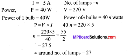
Question 4.
A circuit has a line of 5 A. How many lamps of rating 40W; 220V can simultaneously run on this line safely?
Answer:
Question 5.
A bulb is rated at 200 V, 100 W. Calculate its resistance. Five such bulbs burn for 4 hours daily. Calculate the units of electrical energy consumed per day. What would be the cost of using these bulbs per day at the rate of ₹ 4.00 per unit?
Solution:
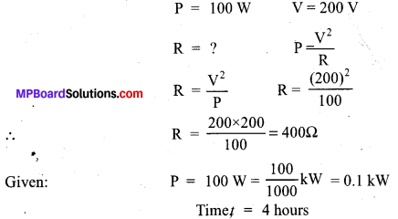
Electrical energy consumed, E = P × t
Energy consumed by 1 bulb = 0.1 × 4 = 0.4 kWh
∴ Energy consumed by 5 bulb = 5 × 0.4 = 2 kWh = 2 units
Cost of electrical energy:
Cost of 1 unit of electricity = ₹ 4
∴ Cost of 2 units of electricity = 4 × 2 = ₹ 8
Question 6.
(a) Describe an activity to show with the help of a compass that magnetic field is strongest near poles of a magnet.
(b) Mention the direction of magnetic field lines (i) inside a bar magnet and (ii) outside a bar magnet.
Answer:
(a) A bar magnet is placed on a sheet of paper and its boundary is marked with a pencil. A magnetic compass is brought near the N-pole of the bar magnet. It is observed that N-pole of magnet repels the N-pole of compass needle due to which the tip of the compass needle moves away from the N-pole. Thus, a magnetic field pattern is obtained around a bar magnet.
(b) Each magnetic field line is directed from the north pole of a magnet to its south pole. The field lines are closest together at the two poles of the bar magnet.
- Inside a bar magnet, the lines of forces start from south pole and end on north pole.
- Outside a bar magnet, magnetic lines of forces start from north pole and end on south pole.
Question 7.
(a) With the help of a labelled diagram, describe an activity to show that a current carrying conductor experiences a force when placed in a magnetic field. Mention the position when this force is maximum.
(b) Name and state the rule which gives the direction of force acting on the conductor.
Answer:
(a) Activity:
- A small aluminium rod (AB) about 5 cm is suspended with two connecting wires horizontally from a stand.
- A strong horse-shoe magnet is placed in such a way that the rod lies between the two poles with the magnetic field directed upwards, the north pole of the magnet vertically below and south pole vertically above the aluminium rod.
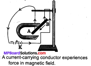
Fig. 13.20: A current-carrying conductor experiences force in magnetic field.
- The aluminium rod is connected in series with a battery, a key and a rheostat.
- When a current is allowed to pass through aluminium rod. Form end B to end A, it is observed that the rod is displaced towards the left.
- When the direction of the current is reversed from A to B, it is observed that the direction of displacement- of the rod is towards the right.
This activity shows that when a current carrying conductor is placed in a magnetic field, a mechanical force is exerted on conductor which makes it move.
The maximum force is exerted on a current carrying conductor only when it is perpendicular to the-direction of magnetic field.
(b) The direction of force acting on the current carrying conductor can be found out by using Fleming’s left-land rule.
According to Fleming’s left-hand rule, hold the fore finger, the center finger and the thumb of your left hand at right angles to one another. If the first finger of your left hand points in the direction of magnetic field and sound in the direction of current, then the thumb will point in the direction of motion or the force acting on conductor.
Question 8.
Study the following current-time graphs from two different sources:
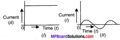
- Use above graphs to list two differences between the current in the two cases.
- Name the type of current in the two cases.
- Identify one source each for these currents.
- What is meant by the statement that “ the frequency of current in India is 50 Hz”?
Answer:
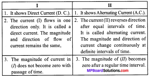
- D.C. – Direct Current.
- A.C.- Alternating Current.
- Source of D.C. → a cell, battery, solar cell, D.C. generator.
Source of A.C. → A.C. Generator. - The frequency of current in India is 50 Hz means the direction of current in India changes 50 times in 1 second.
Question 9.
Explain two disadvantages of series arrangement for household circuit.
Answer:
Disadvantages of series circuits for domestic wiring:
- In series circuit, if one electrical appliance stops working due to some defect then all other appliances also stop working because the whole circuit is broken.
- In series circuit, all the electrical appliances have only one switch , due to which they cannot be turned off or turned on separately.
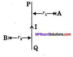
Question 10.
(i) State Maxwell’s right-hand thumb rule.
(ii) PQ is a current carrying conductor in the plane of the paper as shown in the figure. Mention the direction of magnetic fields produced by it at points A and B.
Given r1 < r2 where will the strength of the magnetic field be larger?
Answer:
(i) Maxwell’s right hand thumb rule: The direction of the current is given by Maxwell’s right hand thdmb rule, “If the current carrying conductor is gripped with the right hand in such a way that the thumb gives the direction of the current, then the direction of the fingers gives the direction of the magnetic field produced around the conductor”.
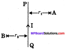
(ii) Since the direction of current in the straight conductor is from Q to P, then according to Maxwell’s right hand thumb rule, magnetic field at point A is inside the paper and at point B is outside the paper. Since r1 < r2 the strength of the magnetic field at A is more than at B because greater the
distance of a point from the current carrying wire, weaker will be the magnetic field produced at that point.
![]()
MP Board Class 10th Science Chapter 13 NCERT textbook activities
Class 10 Science Activity 13.1 Page No. 223
- Take a straight thick copper wire and place it between the points X and Y in an electric circuit, as shown in Fig. 13.8. The wire XY is kept perpendicular to the plane of paper.
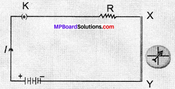
Compass needle is deflected on passing an electric current through a metallic conductor. - Horizontally place a small compass near to this copper wire. See the position of its needle.
- Pass the current through the circuit by inserting the key into the plug.
- Observe the change in the position of the compass needle.
Observations:
- The needle is deflected showing that electric current through the copper wire has produced a magnetic effect.
Class 10 Science Activity 13.2 Page No. 224
- Fix a sheet of white paper on a drawing board using some adhesive material.
- Place a bar magnet in the centre of it.
- Sprinkle some iron filings uniformly around the bar magnet (Fig. 13.9). A salt – sprinkler may be used for this purpose.
- Now tap the board gently.
- What do you observe?
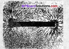
Fig. 13.9: Iron filings near the bar magnet align themselves along the field lines
Observations:
- It is observed that iron filings arrange themselves in a pattern of concentric circles. This shows that iron filings experience a force due to magnetic effect of a magnetic. The lines along which the iron filings align themselves are magnetic field lines.
Class 10 Science Activity 13.3 Pages No. 224,225
- Take a small compass and a bar magnet
- Place the magnet on a sheet of white paper fixed on a drawing board, using some adhesive material.
- Mark the boundary of the magnet.

Fig. 13.10: Drawing a magnetic field line with the help of a compass needle. - Place the compass near the north pole of the magnet. How does it behave? The south pole Fig 13 10: Drawing a magnetic field line of the needle points with the help of a compass needle, towards the north pole of the magnet. The north pole of the compass is directed away from the north pole of the magnet.
- Mark the position of two ends of the needle.
- Now move the needle to a new position such that its south pole occupies the position previously occupied by its north pole.
- In this way, proceed step by step till you reach the south pole of the magnet as shown in Fig. 13.10.
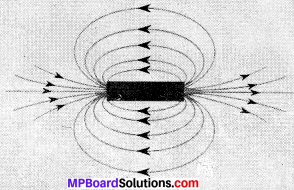
Fig. 13.11: Field lines around a bar magnet. - Join the points marked on the paper by a smooth curve. This curve represents a field line.
- Repeat the above procedure and draw as many lines as you can. You will get a pattern shown in Fig. 13.11. These lines represent the magnetic field around the magnet. These are known as magnetic field lines.
- Observe the deflection in the compass needle as you move it along a field line. The deflection increases as the needle is moved towards the poles.
Observations:
- The magnetic field is strong at the poles due to which deflection increases at the poles as the needle move towards it.
Class 10 Science Activity 13.4 Page No. 226
- Take a long straight copper wire, two or three cells ofl .5 V each, and a plug key. Connect all of them in scries as shown in Fig. 13.12 (a)
- Place the straight wire parallel to and over a compass needle.
- Plug the key in the circuit.
- Observe the direction of deflection of the north pole of the needle. If the current flows from north to south, as shown in Fig. 13.12 (a), the north pole of the compass needle would move towards the east.
- Replace the cell connections in the circuit as shown in Fig. 13.12 (b). This would result in the change of the direction of current through the copper wire, that is, from south to north.
- Observe the change in the direction of deflection of the needle You will see that now the needle moves in opposite direction, that is, towards the west (Fig. 13.12 (b)). It means that the direction of magnetic field produced by the electric current is also reversed.
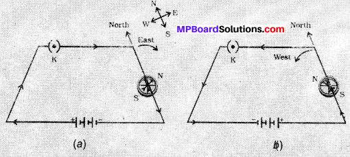
Fig. 13.12: A simple electric circuit in which a straight copper wire is placed parallel to and over a compass needle. The deflection in the needle becomes opposite when the direction of the current is reversed.
Observations:
- As current flow changes its direction from south to north, the needle in the compass moves in a opposite direction that is towards the west. This shows the direction of magnetic filed produced by the electric current is also reversed.
Class 10 Science Activity 13.5 Pages No. 226, 227
- Take a battery (12 V), a variable resistance (or a rheostat), an ammeter (0 5 A), a plug key, connecting wires and a long straight thick copper wire.
- Insert the thick wire through the centre, normal to the plane of a rectangular cardboard. Take care that the cardboard is fixed and does not slide up or down.
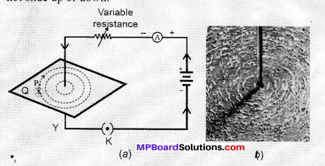
Fig. 13.13: (a) A pattern of concentric circles indicating the field lines of a magnetic field around a straight conducting wire. The arrows in the circles show the direction of the field lines. (b) A close up of the pattern obtained.
- Connect the copper wire vertically between the points X and Y, as shown in Fig. 13.13 (a), in series with the battery, a plug and key.
- Sprinkle some iron filings uniformly on the cardboard. (You may use a salt sprinkler for this purpose).
- Keep the variable of the rheostat at a fixed position and note the . current through the ammeter.
- Close the key so that a current flows through the wire. Ensure that the copper wire placed between the points X and Y remains vertically straight.
- Gently tap the cardboard a few times. Observe the pattern of the iron filings. You would find that the iron filings align themselves showing a pattern of concentric circles around the copper wire (Fig. 13.13).
- What do these concentric circles represent? They represent the magnetic field lines.
- How can the direction of the magnetic field be found? Place a compass at a point (say P) over a circle. Observe the direction of the needle. The direction of the north pole of the compass needle would give the direction of the field lines produced by the electric current through the straight wire at point P. Show the direction by an arrow.
- Does the direction of magnetic field lines get reversed if the direction of current through the straight copper wire is reversed? Check it.
Observations:
- The deflection is the needle changes. If the current is increased, the deflection also increases. It indicates the magnitude of the magnetic field produced at a given point increases as the current through the wire increases.
Class 10 Science Activity 13.6 Page No. 229
- Take a rectangular cardboard having two holes. Insert a circular coil having large number of turns through them, normal to the plane of the cardboard.
- Connect the ends of the coil in series with a battery, a key and a rheostat, as shown in Fig. 13.14.
- Sprinkle iron filings uniformly on the cardboard.
- Plug the key.
- Tap the cardboard gently a few times. Note the pattern of the iron filings that emerges on the cardboard.
Observations:
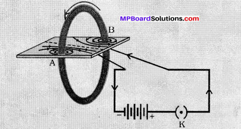
Fig. 13.14: Magnetic field produced by a current carrying circular coil.
Class 10 Science Activity 13.7 Page No. 230
- Take a small aluminium rod AB (of about 5 cm). Using two connecting wires suspend it horizontally from a stand, as shown in Fig. 13.15.
- Place a strong horse-shoe magnet in such a way that the rod lies between the two poles with the magnetic field directed upwards. For this put the north pole of the magnet vertically below and south pole vertically above the aluminium rod (Fig. 13.15).
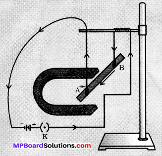
Fig. 13.15: A current carrying rod, AB, experiences a force perpendicular to its length and the magnetic field. - Connect the aluminium rod in series with a battery, a key and a rheostat.
- Now pass a current through the aluminium rod from end B to end A.
- What do you observe? It is observed that the rod is displaced towards the left. Yr- will notice that the rod gets displaced.
- Reverse the direction of current flowing through the rod and observe the direction of its displacement. It is now towards the right.
Why does the rod get displaced?
Observations:
- The rod is displaced due to force exerted on the current – carrying aluminium rod when placed in a magnetic field.
- The direction of force is recedes as the direction of anent through the induction is reversed.
Class 10 Science Activity 13.8 Pages No. 233,234
- Take a coil of wire AB having a large number of turns.
- Connect the ends of the coil to a galvanometer as shown in Fig. 13.16.
- Take a strong bar magnet and move its north pole towards the end B of the coil. Do you find any change in the galvanometer needle?
- There is a momentary deflection in the needle of the galvanometer, say to the right. This indicates the presence of a current in the coil AB. The deflection becomes zero the moment the motion of the magnet stops.
- Now withdraw the north pole of the magnet away from the coil. Now the galvanometer is deflected toward the left, showing that the current is now set up in the direction opposite to the first.
- Place the magnet stationary at a point near to the coil, keeping its north pole towards the end B of the coil. Wc sec that the galvanometer needle deflects toward the right when the coil is moved towards the north pole of the magnet. Similarly the needle moves toward left when the coil is moved aways.
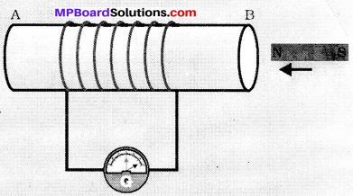
Fig. 13.16: Moving a magnet towards a coil sets up a current in the coil circuit, as indicated by deflection in the galvanometer needle.
- When the coil is kept stationary with respect to the magnet, the deflection of the galvanometer drops to zero. What do you conclude from this activity?
Observations:
- From this activity, it can be concluded that the motion of a magnet with respect to the coil produces an induced potential difference, which sets up an induced electric current in the circuit.
Class 10 Science Activity 13.9 Page No. 235
- Take two different coils of copper wire having large number of turns (say 50 and 100 turns respectively). Insert them over a non-conducting cylindrical roll, as shown in Fig. 13.17. (You may use a thick paper roll for this purpose.)
- Connect the coil-1, having larger number of turns, in series with a battery and a plug key. Also connect the other coil-2 with a galvanometer as shown.
- Plug in the key. Observe the galvanometer. Is there a deflection in its needle? You will observe that the needle of the galvanometer instantly jumps to one side and just as quickly returns to zero, indicating a momentary current in coil-2.
- Disconnect coil-1 from the battery. You will observe that the needle momentarily moves, but to the opposite side. It means that now the current flows in the opposite direction in coil-2
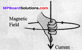
Fig. 13.17: Current is induced in coil-2 when current in coil-1 is changed.
Observations:
- We will observe that the needle of th e galvanometer instantly jumps to one side and just quickly returns to its initial position.